Products
MPVEX
Extremely powerful PBX and suite of business services & solutions created by veteran telephony experts.
MPVISTA
An exciting way to operate your business from literally anywhere with this powerful ERP suite.
Apple
Whether you need a replacement iPhone or an upgrade to the very latest, Metropark is ready.
Alarm.com
Professional-grade security, energy management, and video monitoring solutions for your security.
Eagle Eye / Brivo
Highest level security solutions utilizing state-of-the-art camera & AI technology.
GPS TrackIT
Equip any asset you choose with a GPS device that enables two-way communication.
HP/HPE
HPE & Metropark both work to make what you do matter even more.
Peplink
Boost network data rates, reliability, and flexibility while slashing connectivity costs.
Samsung
Packed with an array of innovative features, Samsung Mobile devices are at the top of the game.
Snom
German designed IP telephony for small and medium sized businesses.
Switchvox
Enables VoIP and traditional calling with each premise-based Switchvox business phone system.
Ubiquiti
Closing the digital divide by building network communication platforms for everyone, everywhere.
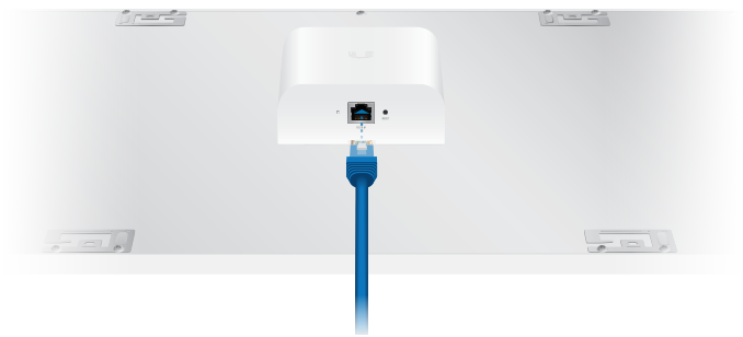
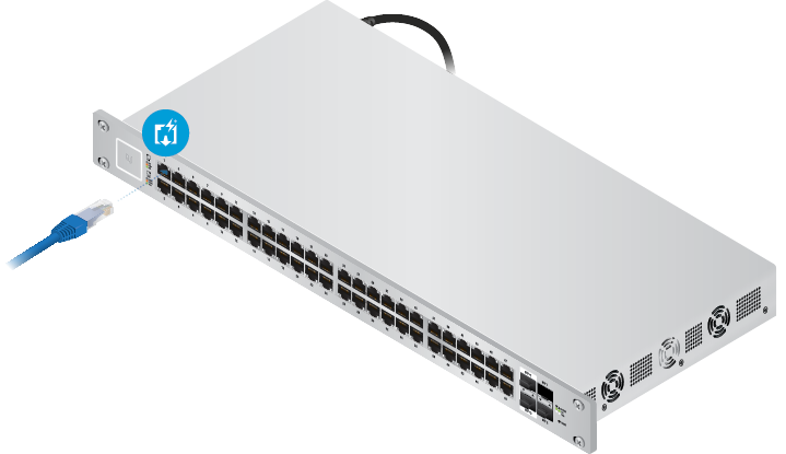
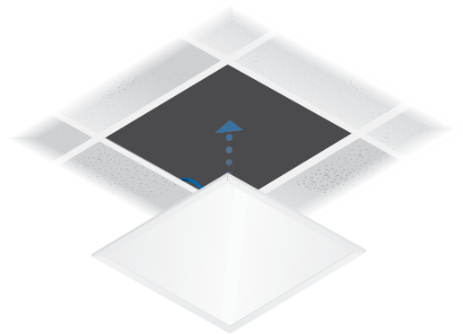
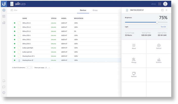
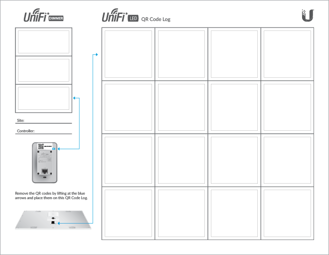
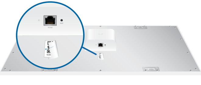
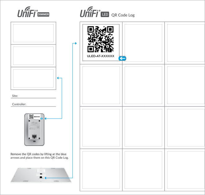
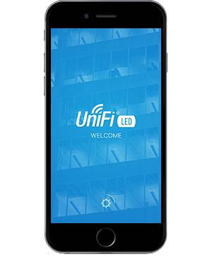
Unifi Lighting
Easily managed low voltage UniFi LED lighting for better business efficiencies.
Willsonpro
Leading all professional-grade, in-building cell signal enhancement technologies.
Yealink
Intended for discerning users with very high expectations of IP phones.
Zyxel
Comprehensive lineup of end-to-end networking solutions that provides a truly integrated platform that works for your business.
Services
By Industry
By Business Need
By business need
By Business Size
Resources
About Metropark
30 years of experience in the realm of cutting edge technologies.

Case Studies
Solutions and the methods that we bring to our wonderful customers.

Careers
We are always looking for qualified, unique people to join our team.

Contact us
Get all of your questions answered in our contact support.
Meet our team
Since 1979, our teams have installed some of the largest phone systems and networks throughout the country.
About Us
About Metropark
30 years of experience in the realm of cutting edge technologies.
Case Studies
Solutions and the methods that we bring to our wonderful customers.
Careers
We are always looking for qualified, unique people to join our team.
Contact us
Get all of your questions answered in our contact support.
Meet our team
Since 1979, our teams have installed some of the largest phone systems and networks throughout the country.